×

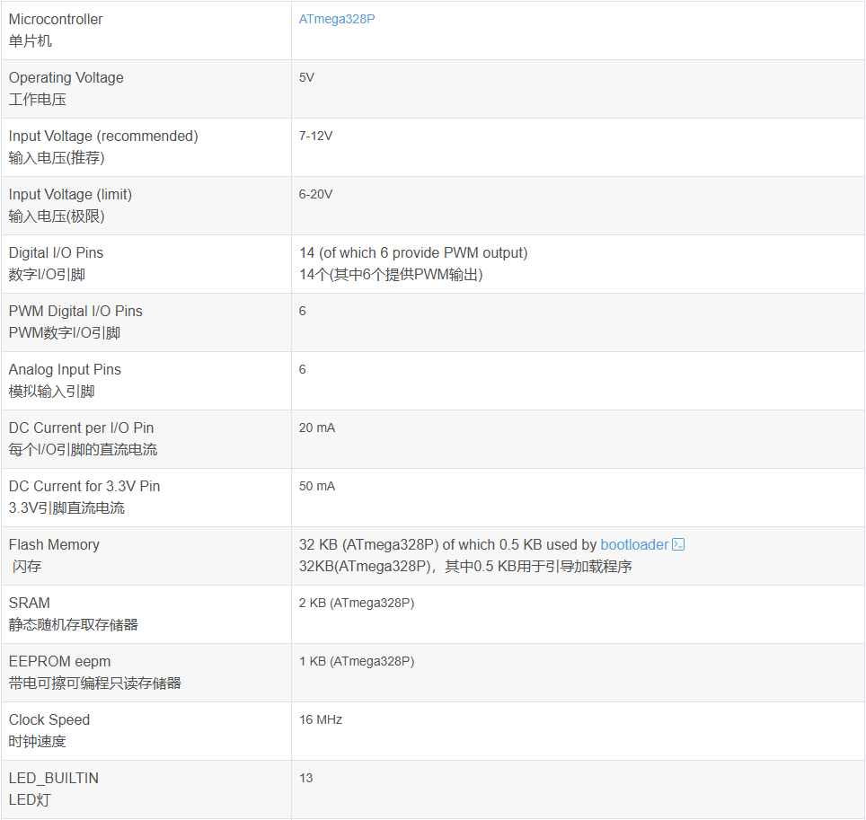
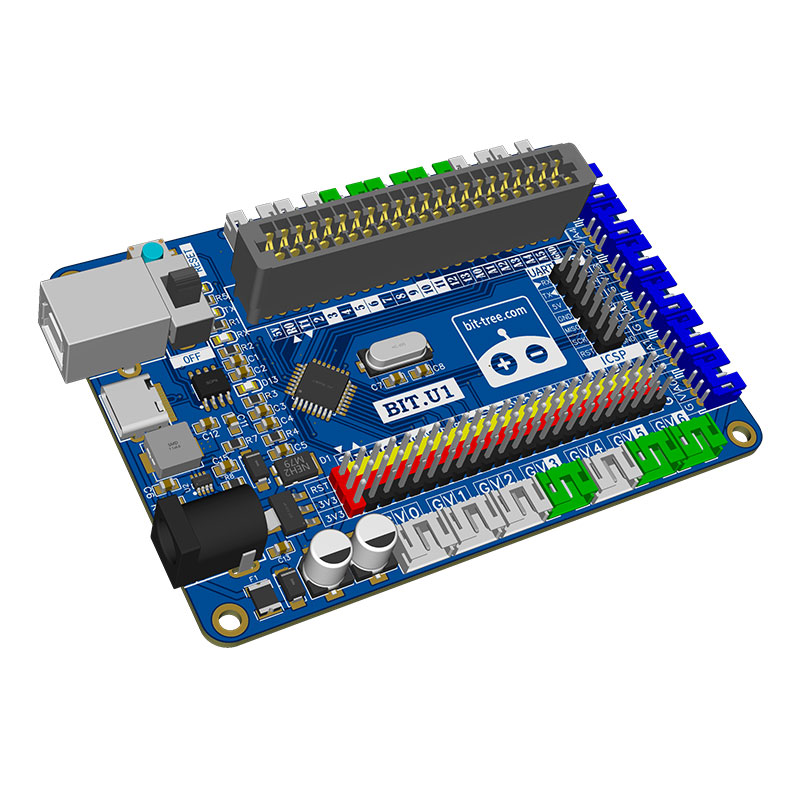
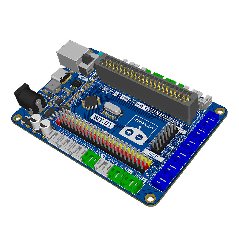
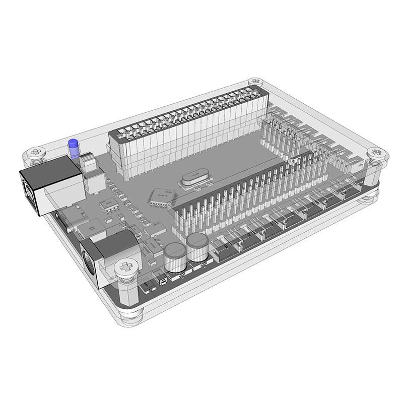
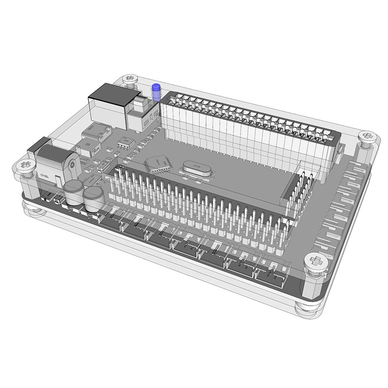
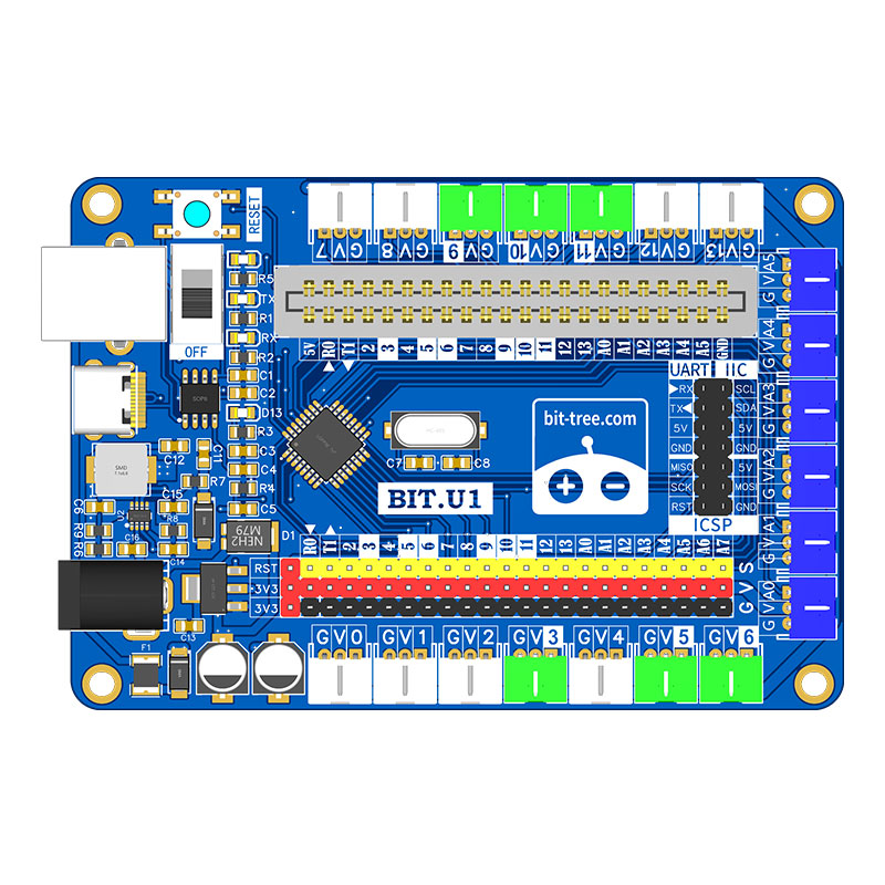
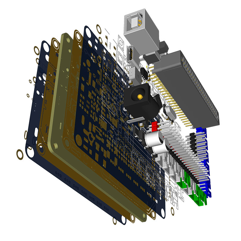
It has 14 digital input/output pins (6 of which can be used as PWM outputs), 6 analog inputs, and a 16 MHz crystal oscillator. The development board has designed both TYPE-B and TYPE-C dual data interfaces, and the serial communication chip uses CH340N. Two LEDs correspond to the TX/RX status respectively. There is a reset button, a main power switch, and a DC power socket (the built-in power conversion chip supports a wide voltage input of 4.5V-18V, with an output voltage of 5V and a maximum output current of up to 5A). An AMS1117-3.3V LDO step-down chip is mounted on the board to provide additional 3.3V power supply. All the microprocessor's I/O ports are brought out through 2.54mm pitch pins along with VCC and GND in parallel. Additionally, 20 color PH2.0/3Pin terminal blocks (PIN, VCC, GND) and a 2.54mm pitch 22P gold finger slot are set for easy insertion of various functional expansion cards, with UART, I2C, and ICSP separately brought out through 2.54mm pitch pins. The board-mounted LED light is consistent with the UNO R3, connected to the MEGA328's D13 pin.
Power Pins:
5V: This is the stable 5V voltage output pin on the development board, which can be used to power other components on the board or external devices.
3.3V: This pin provides a stable 3.3V voltage output, with a maximum drive current of 500mA. This voltage is often used to power certain specific components.
GND: This is the ground pin, serving as the reference for all voltages and currents. In a circuit, the GND pin is used to complete the circuit loop and ensure that the entire circuit has a common logical reference level.
Analog Input Pins:
A0~A7: These six pins are used to read external analog signals. Analog signals are continuous signals that can represent various physical quantities such as temperature, pressure, and light intensity. Arduino reads these analog signals through these pins and then converts them into digital values for use in programs.
Digital Input/Output Pins:
The U1 development board has 14 digital I/O pins, which can be used as input pins to read the logical state (high or low) of external devices, or as output pins to control the switching state of external devices.
D13: This pin is connected to an onboard LED indicator light. Users can control the state of this pin through programming, thereby controlling the on/off state of the LED light. This is a very useful indicator tool that can help users understand the execution of the code.
PWM Pins: Some of the digital pins on the U1 development board (D3, D5, D6, D9, D10, D11) support PWM (Pulse Width Modulation) function. This means that users can control the voltage of these pins through programming, achieving finer control, such as adjusting the speed of a motor or the brightness of an LED.
D0~D12: These pins can also be used as digital input/output pins. Among them, two pins labeled TX (transmit) and RX (receive) are used for serial communication. In Arduino programming, users can use these two pins to exchange data with computers or other devices.
