×


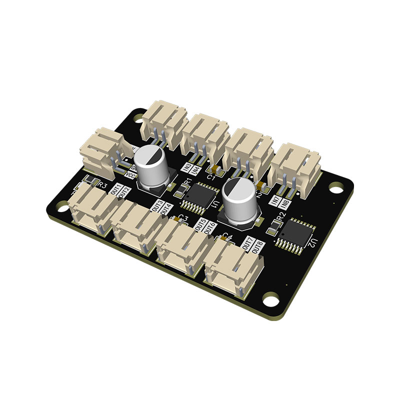
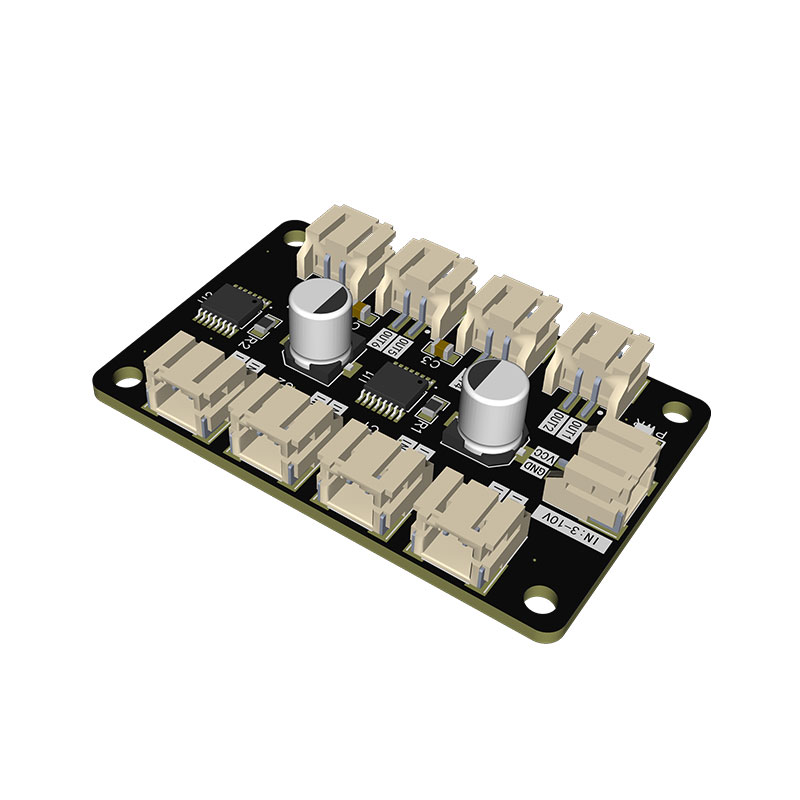
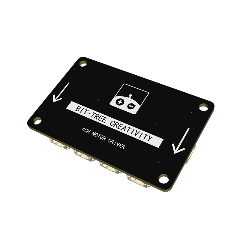
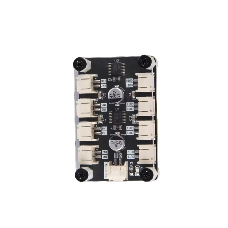
| Parameter Category | Item | Specification Details |
|---|---|---|
| Basic Information | Product Model | A045 |
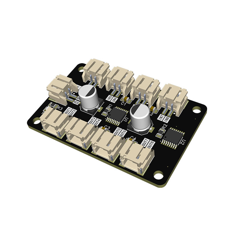
| Basic Information | Module Name | Four‑Channel Motor Driver Module (A045) |
| Basic Information | Core Function | Simultaneously control forward/reverse rotation, dynamic braking and PWM stepless speed regulation for 4‑channel DC motors |
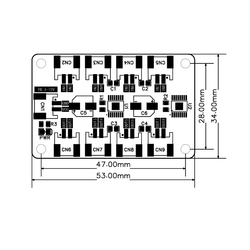
| Basic Information | PCB Dimension | 53.00mm × 34.00mm, with 4 standard mounting holes on PCB |
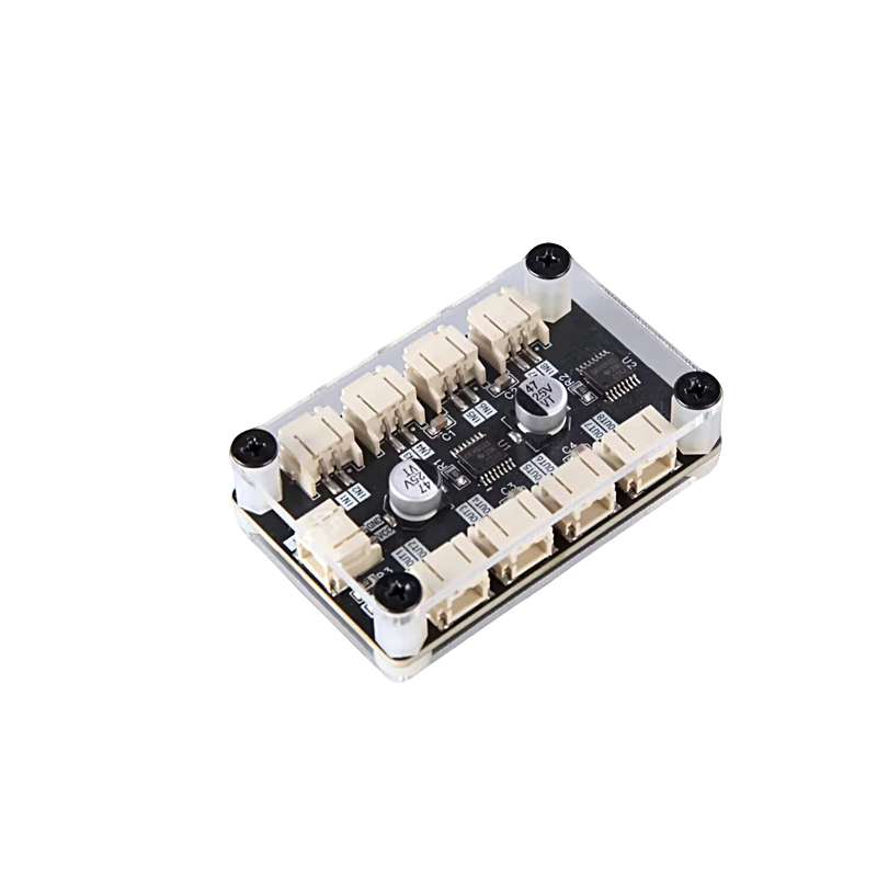
| Basic Information | Product Weight | Weight with enclosure: 20g; Bare‑board weight: 10g |
| Basic Information | Applicable Scenarios | 4‑WD four‑wheel smart car, multi‑joint robot, pan‑tilt, automated multi‑motor equipment |
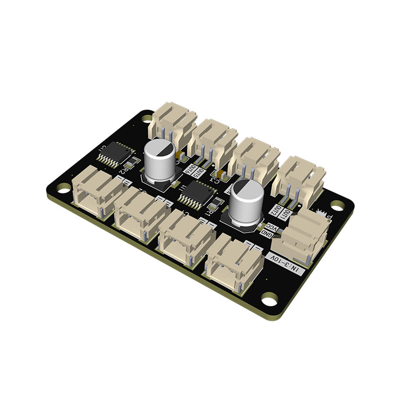
| Electrical Parameters | Motor Supply Voltage | 3V~10V DC, supports lithium‑battery and regulated power supply |
| Electrical Parameters | Logic Control Voltage | 3.3V~5V DC, compatible with full series of Arduino/STM32/ESP32 MCUs |
| Electrical Parameters | Single‑Channel Continuous Output Current | Max 1.5A; higher peak current; heat sink is required under heavy‑load conditions |
| Electrical Parameters | Control Method | 8‑channel logic‑level input IN1~IN8, supports PWM speed regulation |
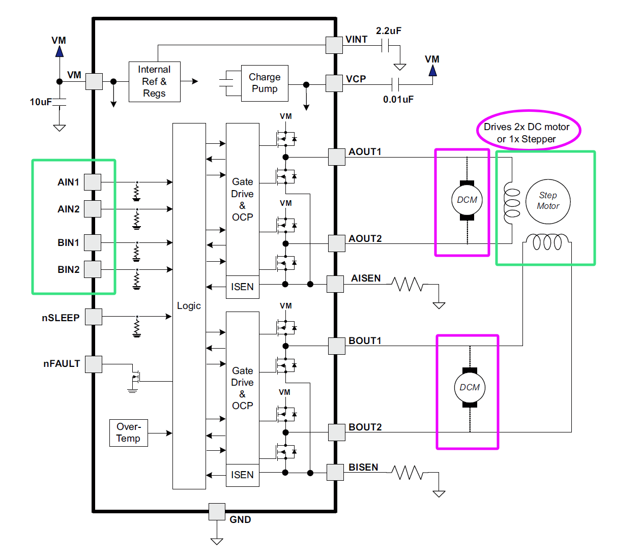
| On‑board Components | Core Chip | U1/U2 Dual H‑bridge driver chips |
| On‑board Components | Peripheral Components | C5/C6 high‑capacity filter capacitors, PWR power indicator LED, C1~C4/R1~R3 filter and current‑limiting components |
| Control Interface CN1 Pin | GND | Power common ground; must share ground with the MCU system |
| Control Interface CN1 Pin | VCC | Positive terminal for logic power supply, connect to 3.3V/5V power source |
| 8‑Channel Control Input Pins | IN1/IN2 | Logic inputs for Motor 1, for direction and brake control |
| 8‑Channel Control Input Pins | IN3/IN4 | Logic inputs for Motor 2, for direction and brake control |
| 8‑Channel Control Input Pins | IN5/IN6 | Logic inputs for Motor 3, for direction and brake control |
| 8‑Channel Control Input Pins | IN7/IN8 | Logic inputs for Motor 4, for direction and brake control |
| Four‑Channel Motor Output Terminals | OUT1/OUT2 (CN6) | Channel 1 motor drive outputs, directly connected to both terminals of the motor |
| Four‑Channel Motor Output Terminals | OUT3/OUT4 (CN7) | Channel 2 motor drive outputs, directly connected to both terminals of the motor |
| Four‑Channel Motor Output Terminals | OUT5/OUT6 (CN8) | Channel 3 motor drive outputs, directly connected to both terminals of the motor |
| Four‑Channel Motor Output Terminals | OUT7/OUT8 (CN9) | Channel 4 motor drive outputs, directly connected to both terminals of the motor |
| General Control Logic‑Forward Rotation | INx High / INy Low, corresponding to OUTx positive, OUTy negative | |
| General Control Logic‑Reverse Rotation | INx Low / INy High, corresponding to OUTx negative, OUTy positive | |
| General Control Logic‑Brake Mode | INx High / INy High; short‑circuit two outputs of the channel for dynamic braking | |
| General Control Logic‑Freewheeling | INx Low / INy Low; motor power‑off without drive, inertial coasting | |
| Speed Regulation Implementation | Input PWM signals to IN1~IN8; adjust duty cycle to control motor speed | |
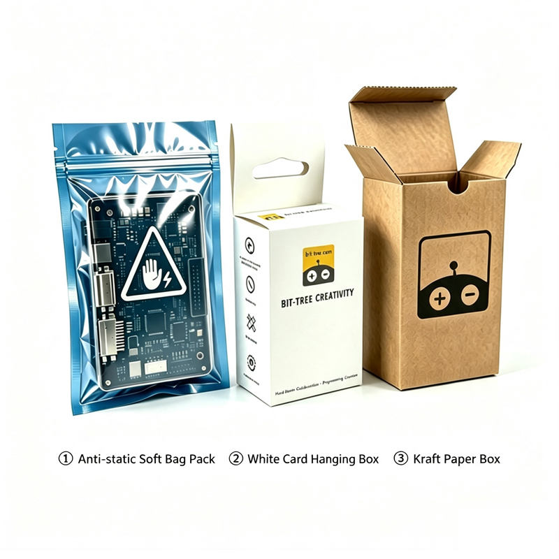
| Packaging Solution | Optional Packaging | ① Anti‑static bag soft package ② White card hanging blister box ③ Kraft paper carton |