×



| Parameter Category | Item | Specification Details |
|---|---|---|
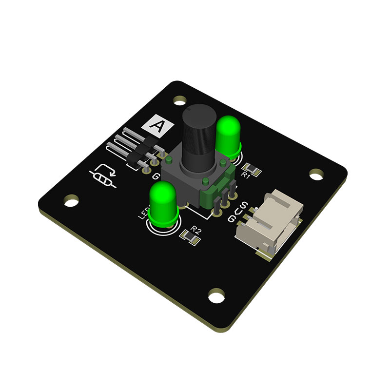
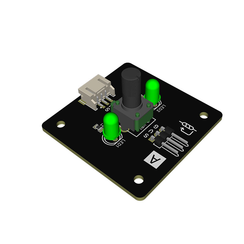
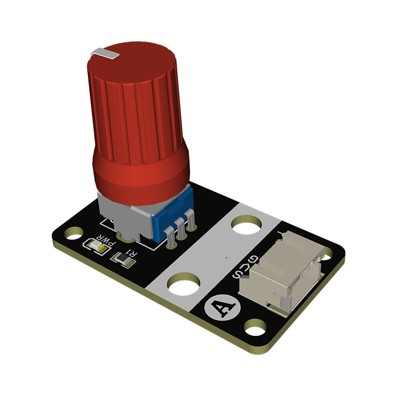
| Basic Parameters | Module Model | Rotary Potentiometer Module (With Status Indicator) (A056). Suitable for analog input scenarios such as volume adjustment, speed control and threshold calibration |
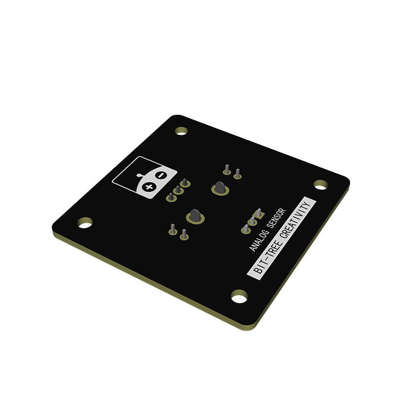
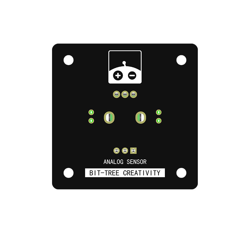
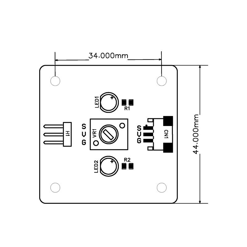
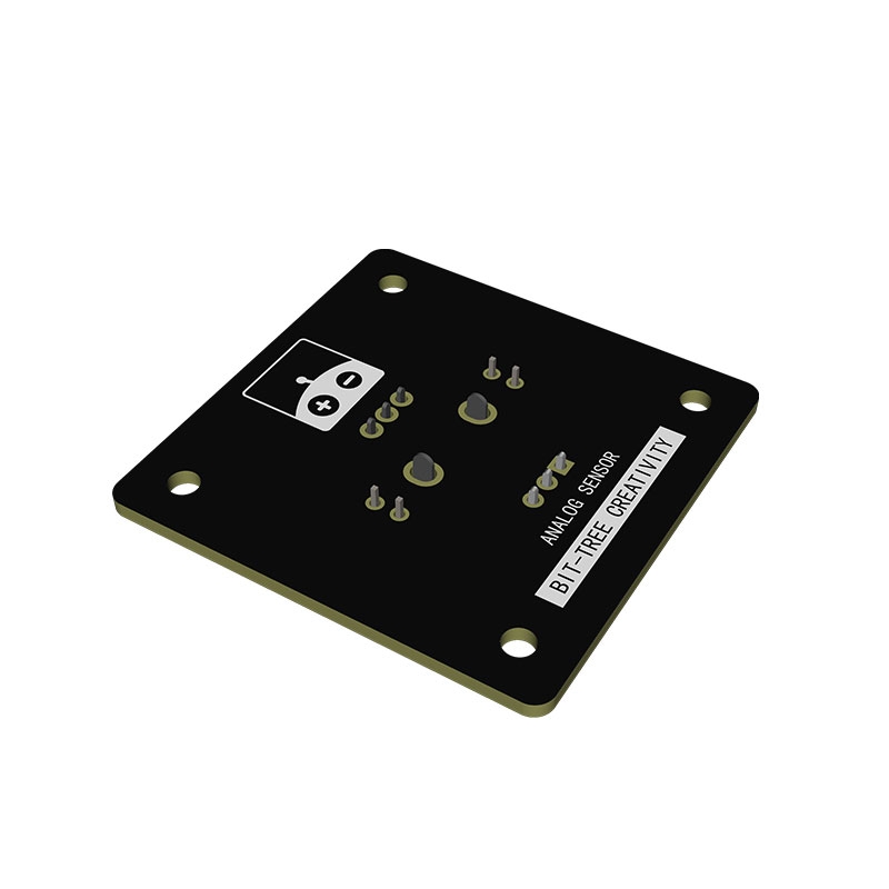
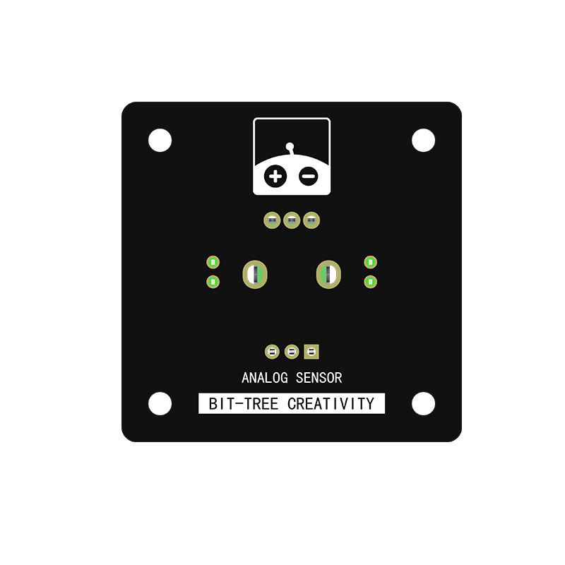
| Basic Parameters | PCB Outline Dimension | 44.00mm × 44.00mm, square standard layout, compatible with embedded installation with panel cutout for general equipment |
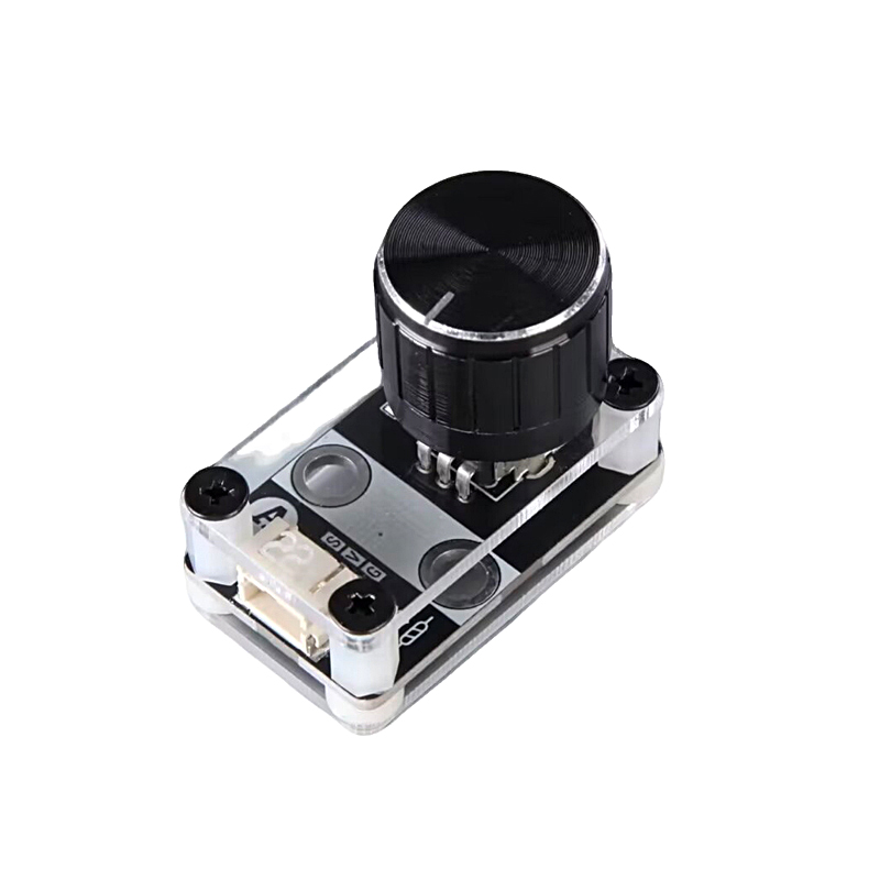
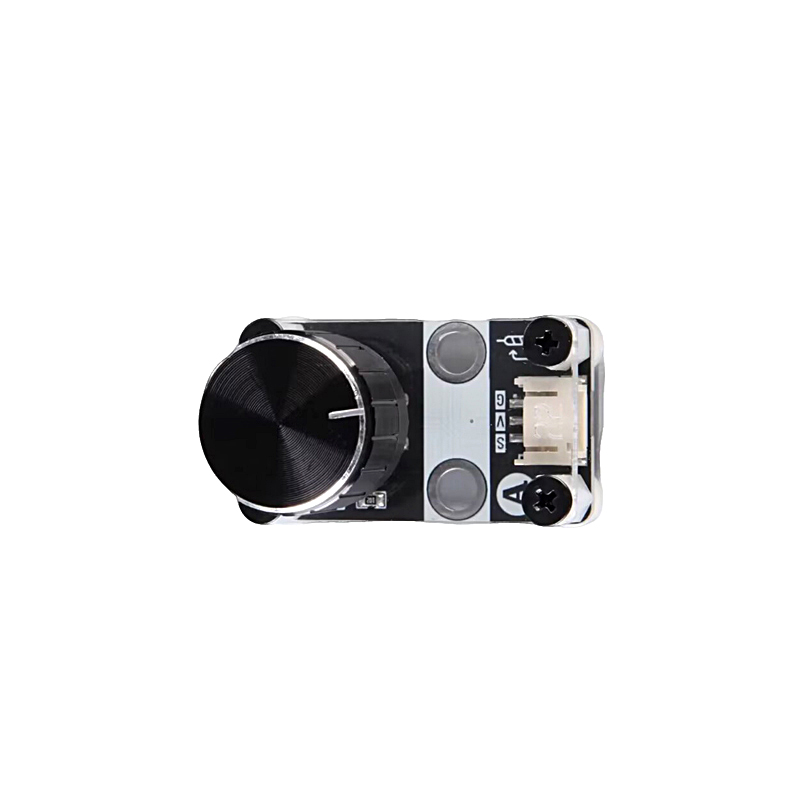
| Basic Parameters | Potentiometer Specification | Single-turn linear carbon film potentiometer, nominal resistance 10KΩ. Equipped with large-diameter aluminum damping knob; resistance changes smoothly without jitter within full rotation stroke |
| Basic Parameters | Status Indicator | 2 SMD green LEDs (LED1/LED2), corresponding to high/low range status feedback. Light on/off logic can be customized via program |
| Basic Parameters | Output Signal | Continuous linear analog voltage output ranging from 0~VCC. Real-time rotation angle value can be converted after acquisition by MCU ADC pin |
| Basic Parameters | Supply Voltage | 3.3V~5V DC wide voltage supply, 5V recommended. Compatible with mainstream 3.3V and 5V MCU systems |
| Basic Parameters | On-board Dual Interfaces | 3Pin straight male Dupont header H1 + 3Pin PH2.0 locking socket CN1. Two wiring methods available, meeting demands of debugging and mass production |
| Basic Parameters | Product Weight | Bare PCB: approx.6g; Finished module with potentiometer, knob, LEDs and all components: approx.14g. Mass production weight tolerance ±0.8g |
| General Interface Pin Definition | VCC | Positive power pin of module. Connect 5V/3.3V DC power to supply power for voltage divider circuit and indicator circuit on board |
| General Interface Pin Definition | GND | Negative power pin of module. Must share ground with external MCU system for unified voltage reference, avoiding voltage drift error in analog sampling |
| General Interface Pin Definition | S | Analog signal output pin. Directly connect to MCU ADC port to transmit divided voltage signal from potentiometer in real time |
| Extended Control Pin | LED1 & LED2 | Independent control pins for two green LEDs, controlled by two MCU IO pins separately. Customizable range light reminder and gear prompt |
| Core Feature - Dual Interface Compatibility | Pre-installed with Dupont header and PH2.0 locking socket. Direct wiring for breadboard experiments and finished equipment assembly | Dupont header supports quick plug-and-play debugging on breadboard; PH2.0 locking socket ensures firm wiring, suitable for development testing and mass production wiring |
| Core Feature - Dual LED Status Prompt | Programmable light logic: LED2 lights at minimum value, LED1 lights at maximum value, both light at midpoint. Visually display knob gear position | No external multimeter required for voltage measurement. Adjustment range can be quickly judged via onboard lights, greatly improving on-site debugging efficiency |
| Core Feature | Large Aluminum Damping Knob | Metal aluminum knob with uniform and smooth damping, anti-slip after long-term repeated manual adjustment. Comfortable hand feel, precise parameter fine-tuning without offset |
| Core Feature | Linear Voltage Divider Output | Output voltage has strict linear proportional relation with rotation angle. Simple angle conversion logic, no non-linear error, convenient program development |
| Core Feature | Four-corner Mounting Hole Design | M3 mounting through holes reserved on four sides of PCB. Can be fixed with screws inside equipment panel or DIY controller housing, neat and stable installation |
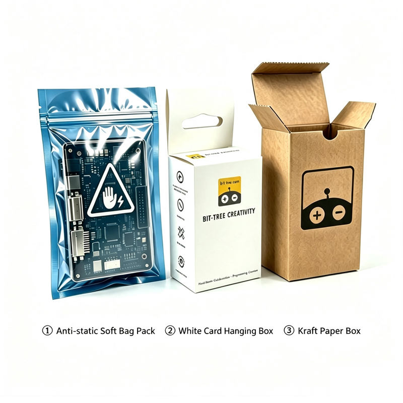
| Packaging Option | Optional Packages | ① Anti-static soft bag ② White hanging-hole card box ③ Kraft paper box |