×


| Parameter Category | Item | Specification Details |
|---|---|---|
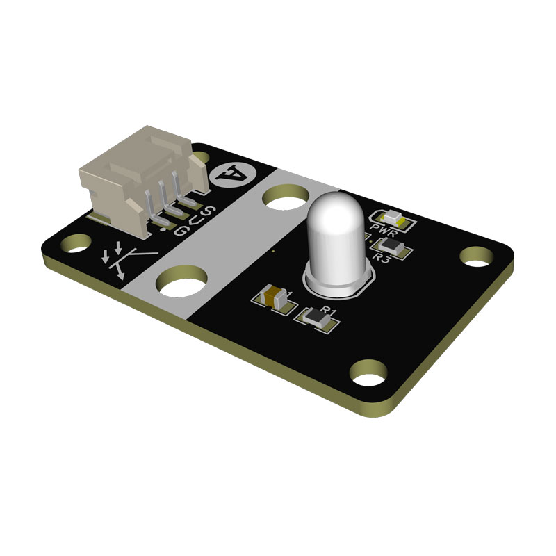
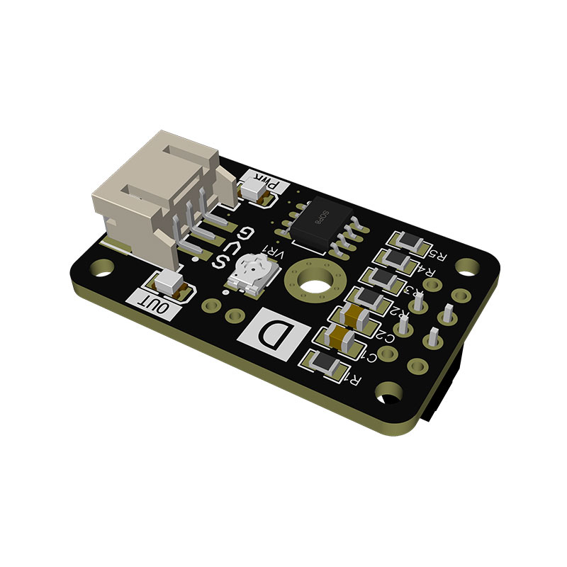
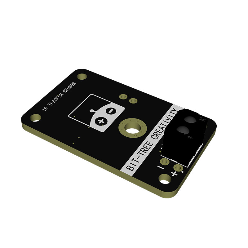
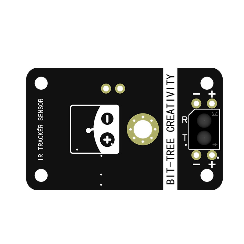
| Basic Parameters | Module Model | Infrared Obstacle Avoidance Sensor Module (Analog Output)(A057). Applied in robot obstacle avoidance, line tracking, object proximity detection and other scenarios |
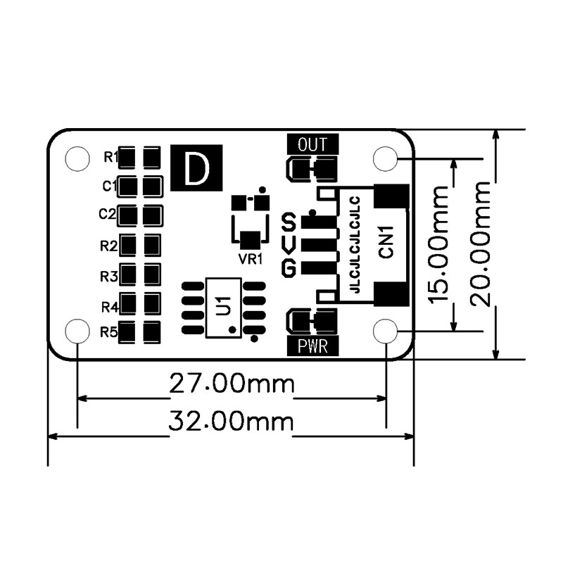
| Basic Parameters | PCB Outline Dimension | 32.00mm × 20.00mm, mini strip layout, suitable for installation of compact equipment with limited space |
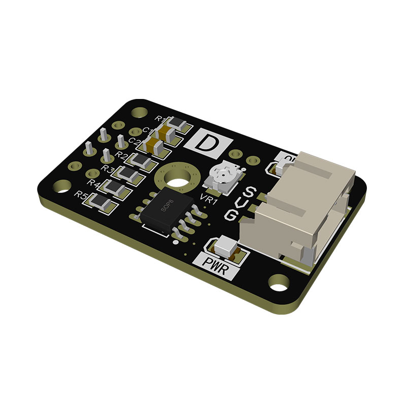
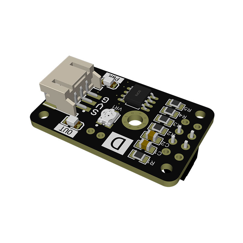
| Basic Parameters | Main Control Chip | ST main controller chip + SOP8 voltage comparator chip (LM393). Equipped with sensitivity adjustment potentiometer VR1 to calibrate detection threshold |
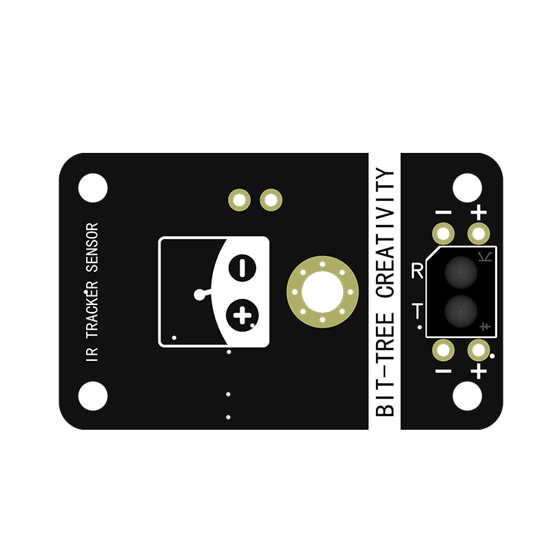
| Basic Parameters | Detection Principle | Infrared reflective photoelectric detection. Infrared light is emitted, reflected by objects and received to judge obstacles ahead |
| Basic Parameters | Effective Detection Distance | Continuously adjustable from 1~15cm. Detection distance is calibrated via potentiometer VR1 to meet different detection requirements |
| Basic Parameters | Output Signal | Standard TTL digital level (OUT pin) + analog AO output. Dual parallel outputs adapt to various acquisition schemes |
| Basic Parameters | Supply Voltage | 3.3V~5V DC, 5V recommended. Compatible with 3.3V MCUs and mainstream development systems |
| Basic Parameters | On-board Configuration | PWR power indicator, OUT detection status indicator, adjustable sensitivity potentiometer. Debug status can be observed directly |
| Basic Parameters | Product Weight | Bare PCB: approx.3g; Finished module with all soldered components: approx.5g. Mass production weight tolerance ±0.5g. Ultra-lightweight with no extra load on equipment |
| 6Pin Header Pin Definition | VCC | Positive power pin. Connect 5V/3.3V DC power to supply power for infrared transmit tube, comparator chip and indicators |
| 6Pin Header Pin Definition | GND | Negative power pin. Must share ground with external MCU system for unified voltage reference to ensure stable signal output |
| 6Pin Header Pin Definition | OUT | Digital detection signal output pin. Connect to general digital IO of MCU. High/low level indicates obstacle existence |
| 6Pin Header Pin Definition | AO | Analog voltage output pin. Connect to MCU ADC acquisition pin. Output analog voltage proportional to reflection intensity |
| Core Feature - Dual Output Function | Digital switch output + analog voltage output. Digital output for front obstacle detection | Digital output directly supports obstacle judgment; analog output quantifies obstacle distance. Two optional signals for different development demands |
| Core Feature - Adjustable Sensitivity | Rotate potentiometer to adjust detection distance for objects with different reflectivity and obstacles | Rotate clockwise to increase detection distance, counterclockwise to decrease. Threshold can be calibrated separately for white, black, wooden and other reflective objects |
| Core Feature - Dual LED Status Feedback | Steady PWR LED means normal power supply; Lit OUT LED means obstacle / black line detected for intuitive observation | No external measuring instruments required. Power status and detection results can be quickly identified via onboard LEDs, greatly simplifying on-site debugging |
| Core Feature - No ADC Acquisition Required | No MCU ADC conversion needed. Obstacle/black line status can be judged directly by reading IO high/low level | Digital output mode only occupies general IO without consuming ADC resources, simple program logic, suitable for entry-level MCU development |
| Core Feature - Ultra-small Size | 32×20mm mini PCB, ideal for micro robots and compact equipment with narrow space | Compact size allows embedding inside equipment, robot chassis and other tight spaces, saving mounting space for miniaturized product design |
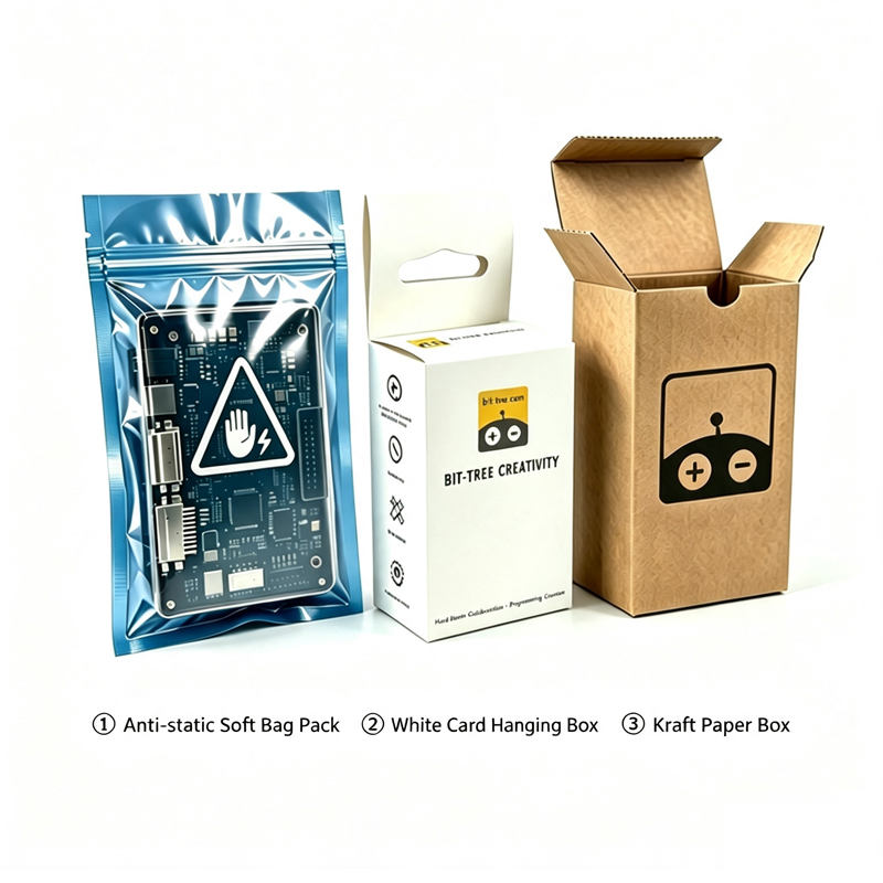
| Packaging Option | Optional Packages | ① Anti-static soft bag ② White hanging-hole card box ③ Kraft paper box |